Deploying Volumetric Capture
The following hardware is needed in order to deploy the Volumetric Capture system:
1 xworkstation (desktop or laptop) (see requirements)K xsensors (either Intel RealSense D415 or Kinect 4 Azure)K xsensor processing units (Intel NUCs recommended, for requirements see here)K xStandard Camera Complete Tripod Units with max height of at least1.6m, (see this)K xVESA 75/100 bracket mounts (see this)1 xnon-blocking Network Switch with at least1GBpsbandwidthK + 1 xEthernet cables (of at least100Mbps)
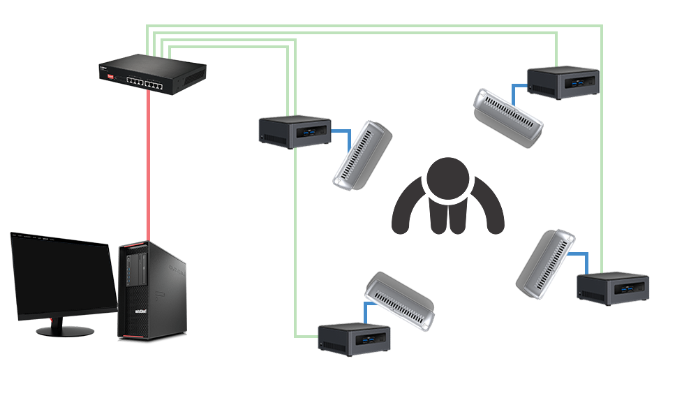
Deployment is not restricted to the availability of internet, with the connectivity of the different components (using 4 D415 sensors) depicted in the following diagram, which also showcases its scalable, distributed architecture:
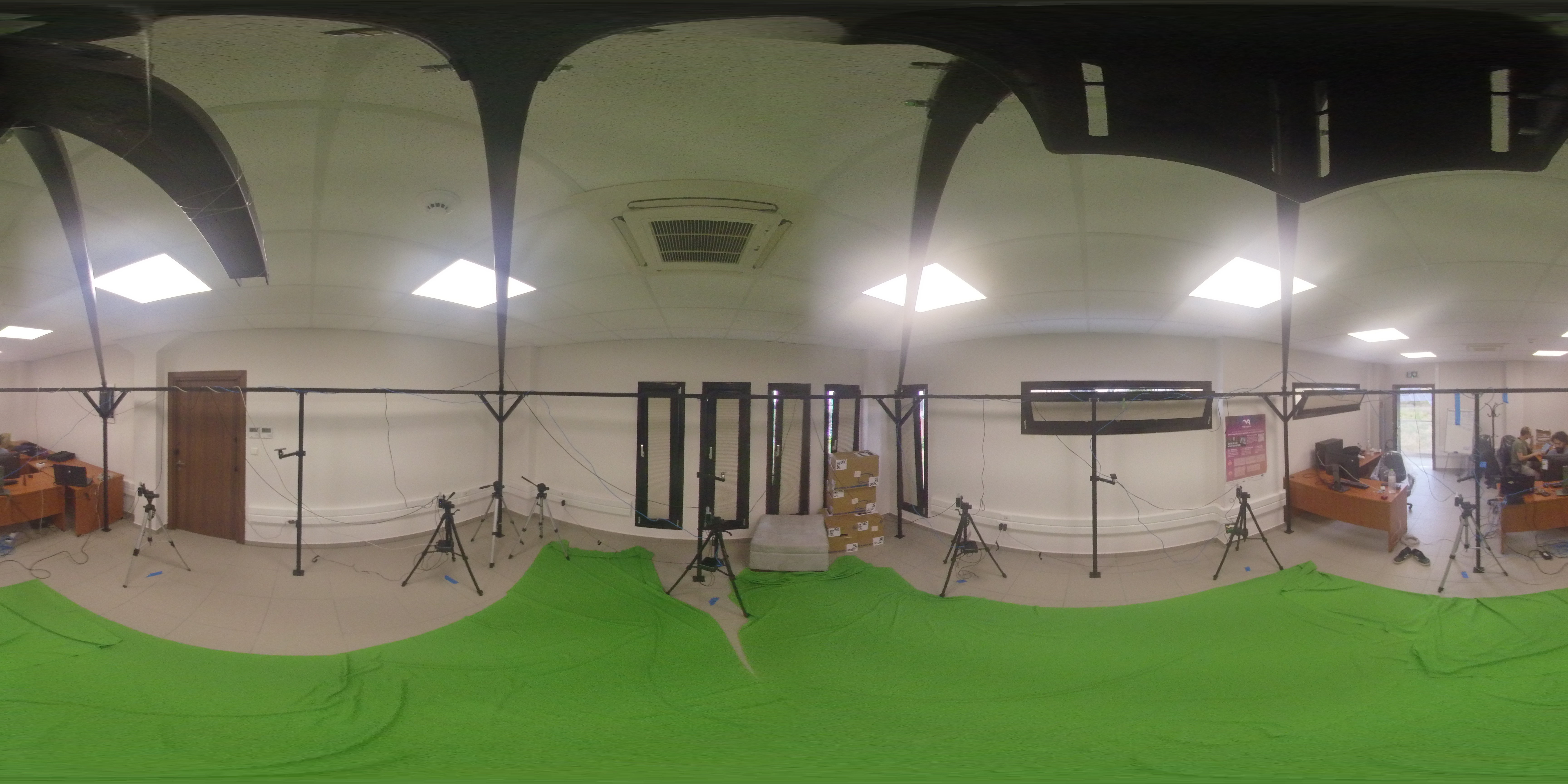
The following image shows a panoramic view of a volumetric capturing setup with 6 Kinect 4 Azure sensors.
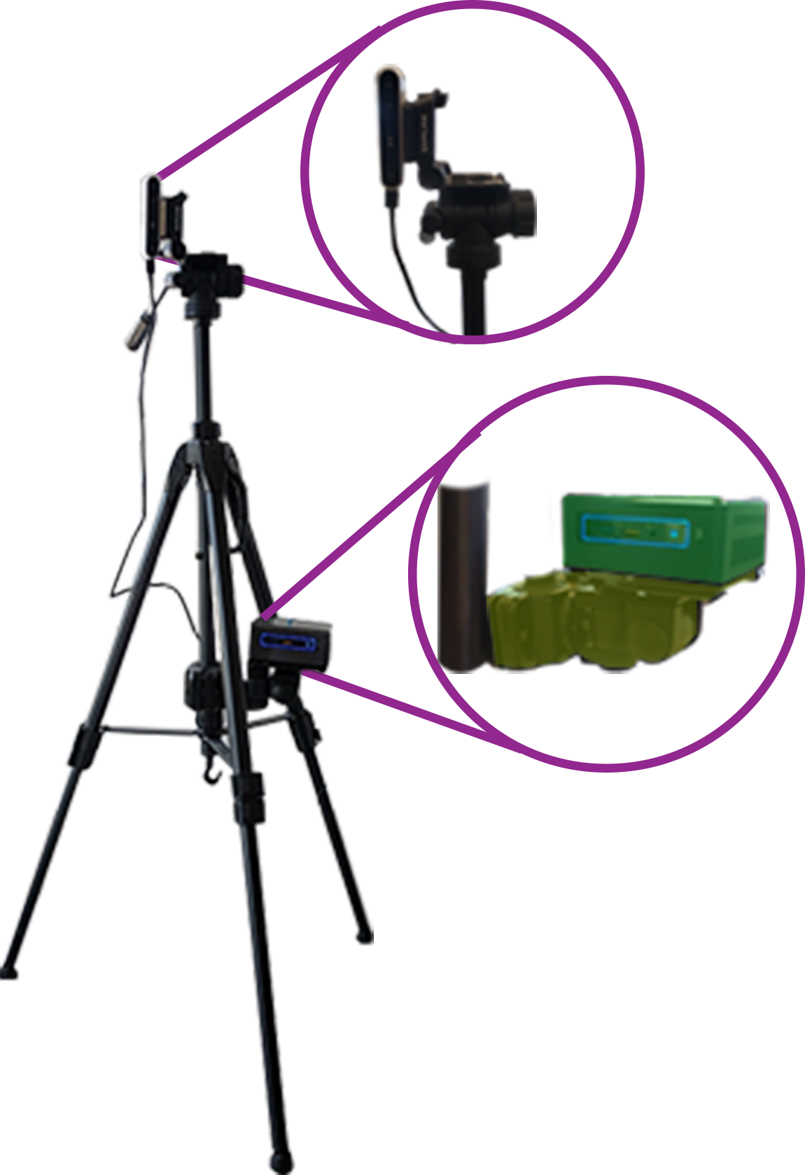
Each one is mounted on a tripod, with each tripod carrying a VESA mounted Intel NUC mini-PC as seen in the following image:
Here you can find instructions regarding Hardware setup, and the assembly of the capturing station.
Tripod Unit Assembly
The assembly of each tripod unit, comprising the tripod, a mini-PC, and a sensor (an Intel RealSense 2.0 D415 in this case) is illustratively explained:
Initially, each sensor is mounted on its corresponding tripod (just like a normal digital camera), by screwing the sensor on the tripod’s base.
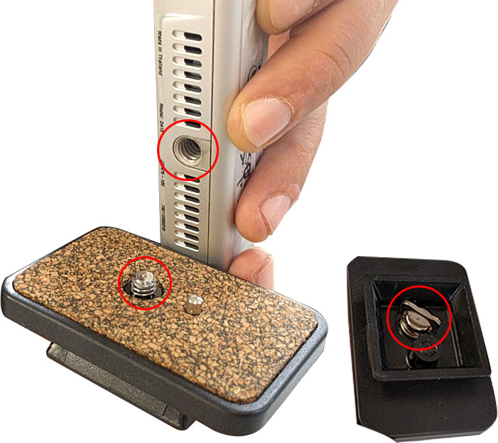
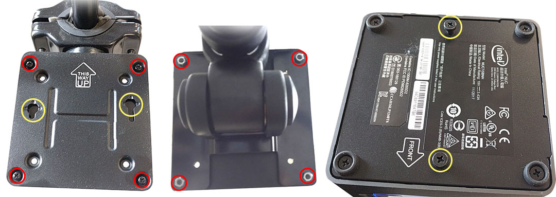
The Intel NUC mini-PCs also include a VESA 75/100 base mount. This should be screwed on the tripod bracket mount. In order to do this you will need 4 nuts of the same diameter as the screws (you can use the screws that come with the NUCs), so you can lock the VESA mount on the bracket mount (red). Then the bracket mount can be mounted on the tripod’s main column with the help of the allen screws that come with the bracket mount. Finally, the NUC is placed on the VESA mount with the help of the longer screws (included in the NUC package), and is then slided on the screw channels (yellow).
Next, connect each sensor with its corresponding mini-PC, via the sensor’s
USB3.0cable.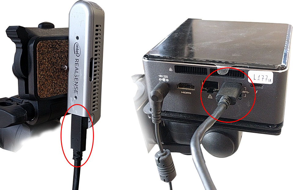
Then, connect each mini-PC to the network switch, with network
CAT5e(or better) Ethernet cables.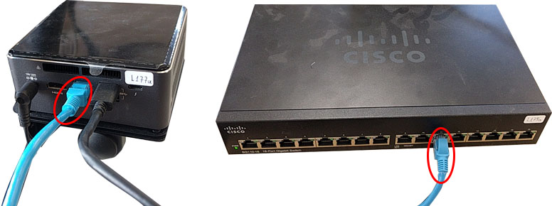
Finally, connect the network switch and the workstation with another network cable.
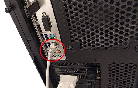
The Capturing Station’s setup is complete.
Note: If you require hardware synchronization, then the parts for assembling the hardware syncing cables are different for each sensor: