Multi-sensor Synchronization
The Volumetric Capture system offers synchronized recording for multiple. Synchronization is achieved on play-back after:
- Assuming intra-device color & depth stream synchronization (or best effort in some devices, allowing for a small
msdesync offset), - Configuring inter-sensor hardware synchronization (optional - best required for best results when capturing fast performances),
- Placing all sensors on the same global timeline
Hardware Synchronization
For the hardware aspects (assembling, cabling), see the respective sections for Intel RealSense 2.0 D415 and Microsoft Kinect 4 Azure.
Once the synchronization cables have been assembled and connected to the sensors in a specific topology (daisy-chain or star), a master device needs to be setup that will trigger the other (slave) devices. This is achieved through the drop-down menu in the Devices widget, where a single device is selected as the master.
Software Synchronization
While multi-device hardware synchronization is useful for acquiring synchronized frames on the device side (i.e. every device will acquire a frame at the peak of the master device’s signal), the mini-PCs that control each device may not be in sync among themselves or with the workstation. What this means is that each stream’s starting point in time is not aligned, and their clocks as well. Therefore, while the frames are captured by the sensors at the same time (triggered), we still need to estimate temporally grouped multi-sensor frames.
As a result, we need to synchronize the clocks of the sensor processing units and the workstation. Then we can align them all to a single global timeline (i.e. the workstation’s) and perform grouping to guarantee the playback’s synchronized state.
The Volumetric Capture system uses the IEEE 1588 precision time protocol (PTP) for software synchronization and provides three PTP-style software synchronization modes:
pyPTPis an external python compiled executable for calculating the clock offset of every mini-PC to the main-PC.nPTPis a native implementation of the same functionality as pyPTP.PTPdis a native daemon-like implementation that is triggered periodically while the main program runs, updating each mini-PC’s offset automatically at each period.
Note that pyPTP is not implementing the IEEE 1588 standard and works on a best effort basis
Native (nPTP and PTPd) IEEE 1588 PTP requires allowing UDP connections on port 320 (both incoming and outgoing) on the workstation’s firewall as well as port 321 on the mini-PCs.
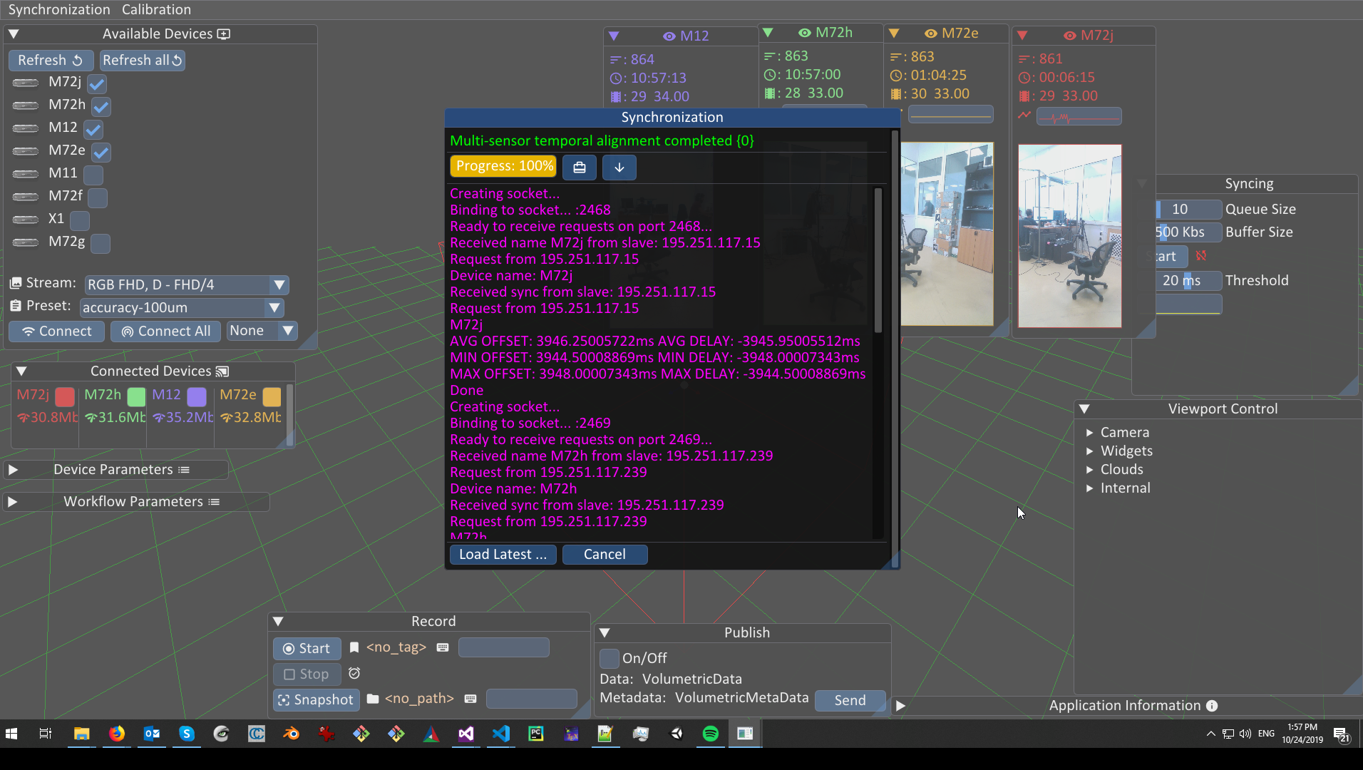
Synchronization is performed via the Synchronization Toolbar menu.
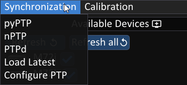
The options are the following:
pyPTP: Runs Python-based synchronizationnPTP: Runs native PTP synchronizationPTPd: Runs continuousnPTPsynchronizationLoad Latest: Loads the latest synchronization resultsConfigure PTP: Enables PTP methods’ parameter configuration
PTP Configuration
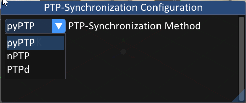
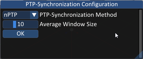
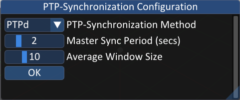
The PTP synchronization methods compute the average offset of the distributed sensor processing unit clocks with the workstation. Through the configuration window you can modify the aggregation window size for nPTP and PTPd, the triggering period for PTPd, while pyPTP is not configurable. You can select which synchronization method you want to configure from the drop-down menu on the PTP configuration window.
You can select which PTP configurations to modify by selecting the corresponding PTP method from the drop-down menu on the PTP-Synchronization Configuration widget.
Running PTP synchronization
pyPTP
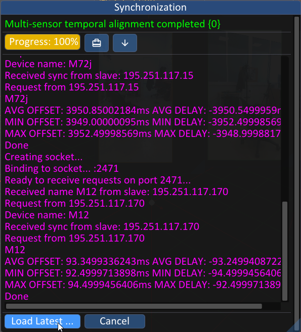
When pyPTP is running (by clicking the corresponding option on the Synchronization menu) a popup will appear on which the synchronization results will be displayed when the synchronization process finishes. You should click the Load Latest button in order to load the calculated synchronization results.
nPTP
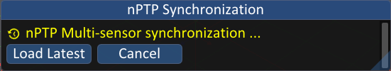
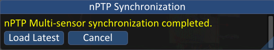
When nPTP is running (by clicking the corresponding option on the Synchronization menu) a popup will appear that will inform the user when the process is finished. Again, you should click the Load Latest button to load the calculated synchronization offsets.
PTPd
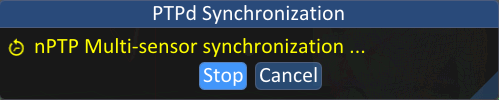
When the PTPd option is selected from the Synchronization menu, a pop-up will appear prompting the user to start the synchronization process.

Once the user clicks the Start button the synchronization will start and the calculated clock offsets will be loaded automatically. The calculation of the synchronization offsets will be triggered every 2 secs by default (a parameter that can be modified from the PTP-Synchronization Configuration widget). In order to stop the process, the user must select PTPd from the Synchronization menu, and click the Stop button.
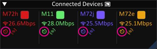
Finally, the user can check if synchronization offsets are loaded for every device from the Devices widget where a clock icon will be displayed under every device name if the synchronization offsets are loaded. Further, mousing over this icon shows the offsets in a human readable format.
Hardware Synchronization Result
To showcase the benefits of hardware synchronization in a performance capture context with fast actions, two distinct recordings are presented below, one using hardware synchronization and another one without, both from very fast performances.
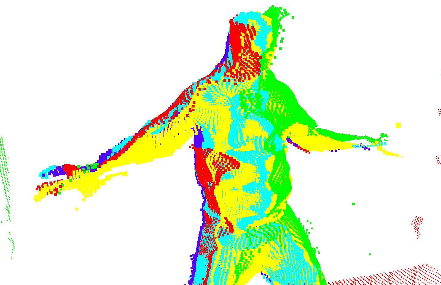
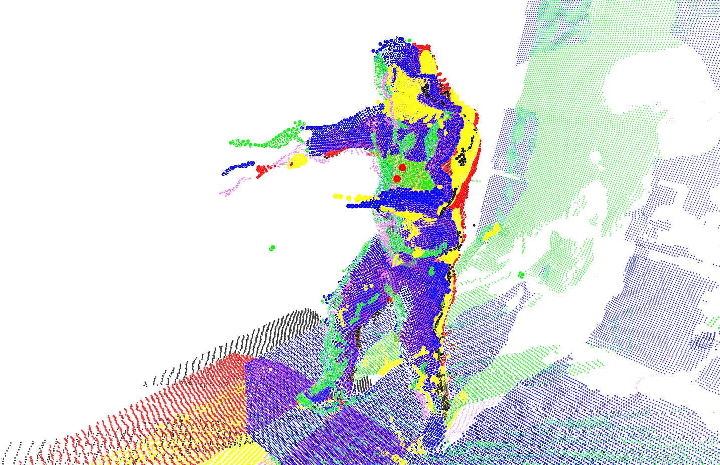
On the left side, we have hardware synchronization enabled, where it is apparent that the volume of the fast moving limbs are better preserved compared to the right side which has no hardware synchronization where each partial view is split.
Note that these recordings were conducted with K4A which due to its time-of-flight principle, integrates 4 measurements. This adds an inherent error factor during fast motions.