The Centralized VolCap Application
Volumetric Capture Controller: A Remote Multi-sensor Controller Interface
Usage: volcap.exe [OPTIONS]

Options:
    -h,--help                                           Print this help message and exit
    -l,--local_IP TEXT                                  Host IP address
    -b,--broker_IP TEXT                                 Broker's IP address
    -u,--broker_username TEXT=volumetric                Broker's Login Username
    -p,--broker_password TEXT=capture                   Broker's Login Password
    -d,--device_repo_path TEXT=device_repository.json   Full path to device_repository.json
    -v,--verbose                                        Verbosity flag
Running the application
The application requires the availability of a device repository file, communication with the message broker (broker_IP, broker_username, broker_password) and additionally broadcasts a spawning message at a single network interface (local_IP). However, its default values are set to localhost and the volumetric/capture username/password. Details about the installation of the RabbitMQ message broker and the registration of the sensors in the device repository can be found at the Configuration section. If the configuration has been set up as proposed, it will match the default arguments, and with the RabbitMQ installed on the workstation running VolCap, then a single double-click on the volcap.exe suffices.
Workflow
Preparation
- Add each sensor to the device repository
- Plug the sensor on the workstation to add this connected device to the device repository (note: only a single sensor must be connected each time).
- Follow the instructions on the device repository section of the Configuration to register the sensor and add it in the
device_repository.json. - Repeat for all the sensors you will be used (and for each new sensor).
If the devices’ intrinsic parameters are not saved in the device repository you will not be able to calibrate the system
- Starting the VolCap application
- First, make sure that the devices are plugged on the sensor processing units (i.e. Intel NUCs), and that each one of them, as well as the workstation, are connected to the network switch.
- When you first start the VolCap application (
volcap.exe) it should connect automatically to the RabbitMQ broker running on the workstation (localhost). If that is not the case, or if the RabbitMQ broker is set up on a different IP, you can start VolCap using the respective command-line arguments:
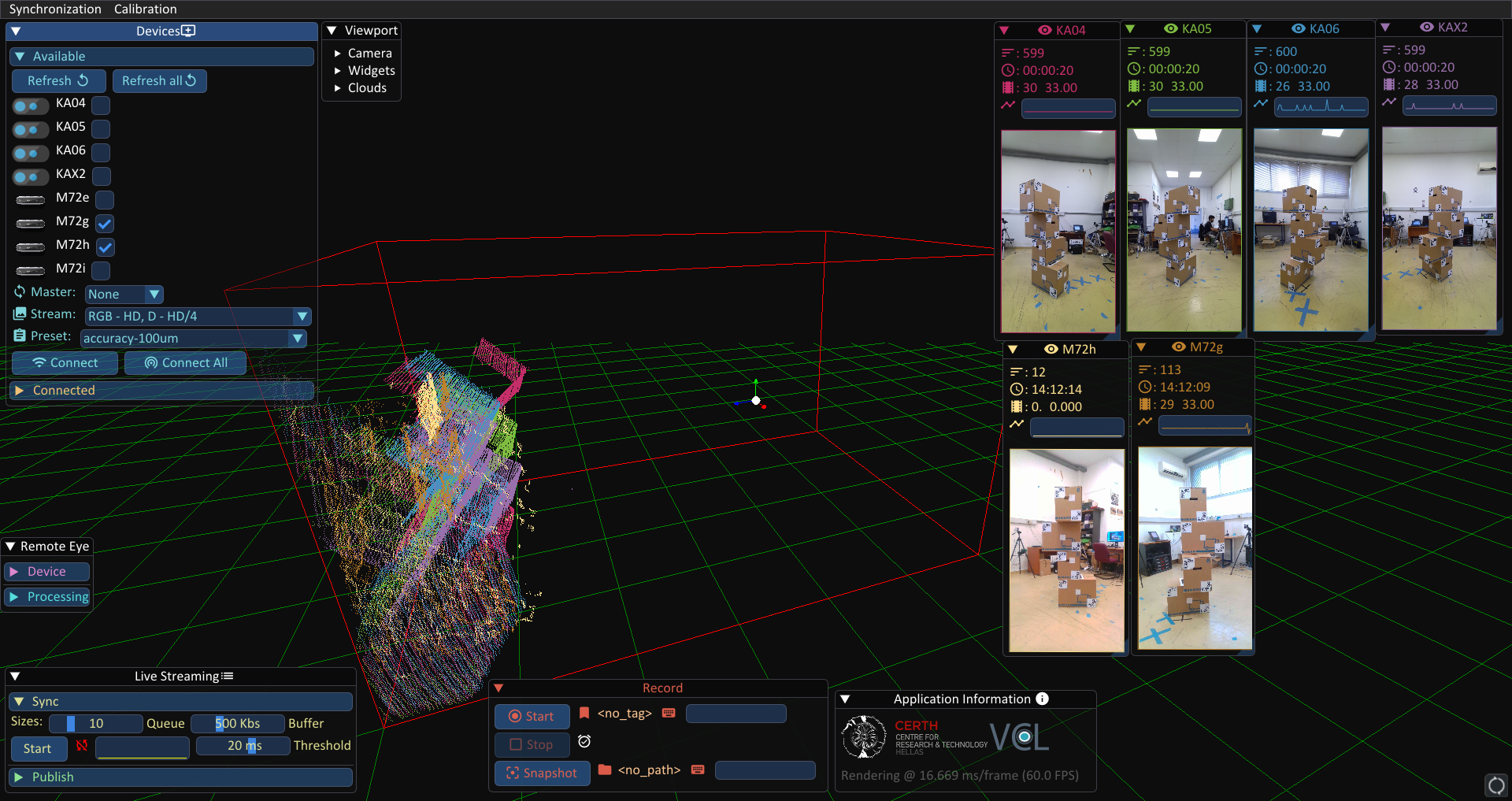
volcap.exe -b <rabbit_mq_broker_local_ip> -u <rabbit_mq_username> -p <rabbit_mq_password>The application’s GUI when the application starts:
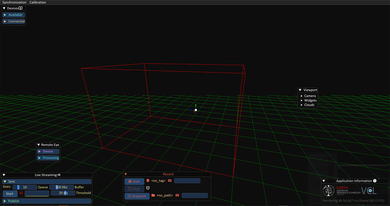
The GUI is divided in widgets. Each widget is responsible for a different aspect of the application workflow.
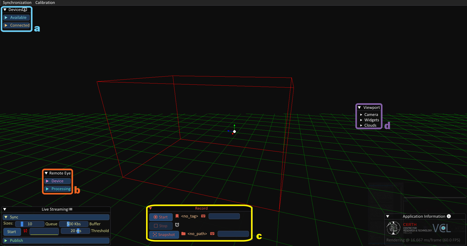
Devices WidgetRemote Eye Configuration WidgetRecording WidgetViewport Control Widget
Application Workflow
1. Connecting devices/sensors
When you first start the application, each of the registered devices (in the device_repository.json) should appear on the Devices Widget with its given user-friendly name. From this widget you can connect all of the devices at once (Connect All), or connect each device separately (select, and Connect). In addition, you can modify the devices’ connection stream profile (Stream), parameters preset (Preset), or configure the master device when using HW sync (toggle next to Connect All). Specifically:
Connect single device:
In order to connect a single device you have to select which device to connect by clicking on the checkbox next to that device, and click the
Connectbutton. If you want to connect all of the devices at once, you can click theConnect AllButton.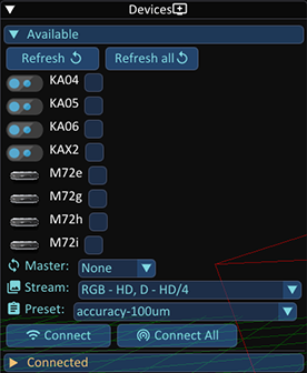
Selecting the connection stream profile.
Stream profiles control the resolution of the color and the depth streams. The available stream profiles are the following:
RGB - HD, D - HD/2:1280 x 720color &640 x 480(Intel RealSense 2.0) or640 x 576(Microsoft Kinect 4 Azure) depth resolutionRGB - HD, D - HD/4:1280 x 720color &320 x 180(Intel RealSense 2.0) or320 x 288(Microsoft Kinect 4 Azure) depth resolutionRGB - HD, D - HD/4:640 x 360color &320 x 180(Intel RealSense 2.0) or320 x 288(Microsoft Kinect 4 Azure) depth resolution
If you have a slow connection, or if the network switch is not unmanaged you can select a profile with lower resolution than Full HD. The default selected profile is
RGB - HD, D - HD/2which has no problems with the recommended network switch for up to6K4A sensors. For reduced bandwidth in order to accomodate more devices, we recommend theRGB - HD, D - HD/4stream profile.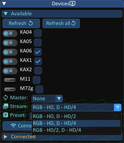
Set the master device for HW device synchronization
From the drop-down menu next to the
Connect AllButton, you can select which device will be the Master device in a Hardware sync scenario. In order to use hardware synchronization, you need to have the HW sync cables assembled and connected to the sensors in either daisy-chain or star configuration. More details can be found at the Synchronization section for the process itself, and for assembling the HW sync cables at the respective sections for the Intel RealSense 2.0 D415 and the Microsoft Kinect 4 Azure.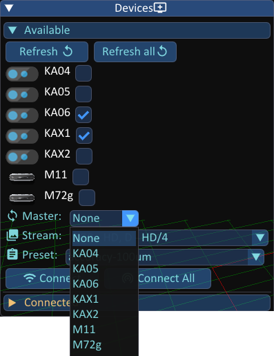
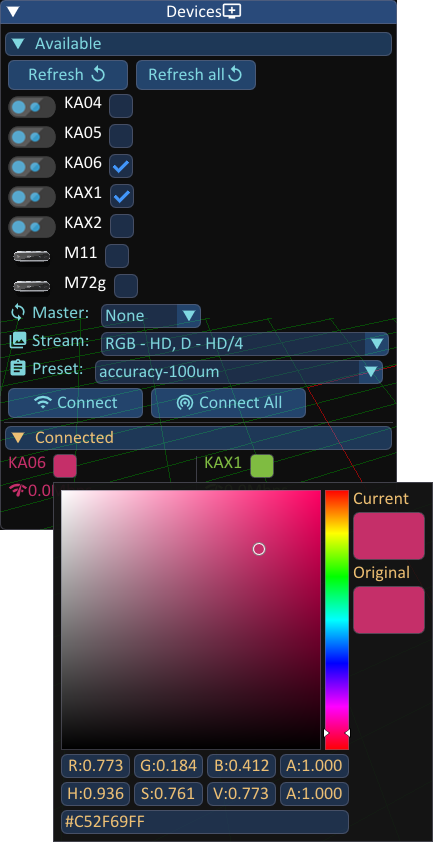
Finally, when all of the devices are connected, each device viewport as well as the parameters of all the other widgets should appear on screen.
For each device, their real-time bandwidth consumption is displayed, along a color picker that sets that device’s color.
Note: Mousing over the names or icons in this widget displays a tooltip with the device’s IP which is helpful when needing to access the mini-PC for troubleshooting (via remote desktop or TeamViewer). In addition, pressing CTRL+C when mousing over will copy the IP in the clipboard.
2. Parameterizing devices
The VolCap application aims to be as configurable as possible. Experienced users have the ability to modify the parameters of the connected devices, by using the Remote Eye Configuration widget. You can modify a specific parameter for all the devices at once, or for each device separately.
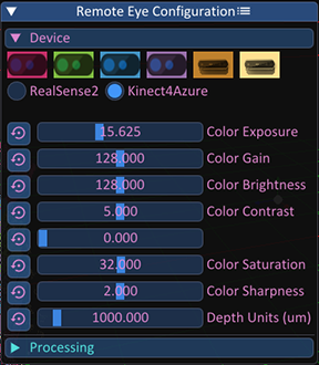
Each sensor comes with different configuration capabilities. An indicative list of parameters that can be modified are:
Color ExposureColor GainColor BrightnessColor SharpnessColor HueColor SaturationMaximum Distance (Depth Sensor)Depth ExposureDepth GainLaser Powerset/unset Color Auto Exposureset/unset Depth Auto Exposure
When modifying device parameters using the sliders in the widget, then by default the modification will be applied to all of the connected devices. In order to modify parameters of a specific device, you have to first click on colored buttons depicting each device.
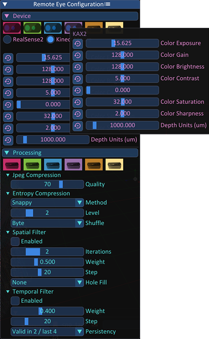
Apart from the devices’ parameters, users can also modify processing parameters. These currently include compression settings (for color and depth) and depth filtering settings. The latter are only available for the Intel RealSense 2.0 D415 devices. For the former, jpeg compression parameters only apply to the RGB - HD stream profiles for the Kinect 4 Azure device.
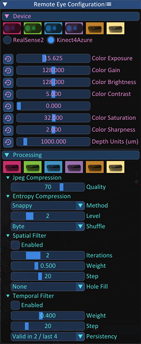
More specifically:
- Jpeg Compression (Color stream compression):
Quality: Modifies the quality of the color stream compression (higher value means higher quality)
- Entropy Compression (Depth stream compression):
Method: You can choose one of the following entropy compression methods:BloscLz4Lz4HCSnappyZlibZstd
Level: The level of compression (higher value means better compression)Shuffle:ByteorBit
Spatial Filter(Depth Stream Spatial Filter):Parameters correspond to those of the RealSense 2.0 SDK.
Temporal Filter(Depth Stream Temporal Filter):Parameters correspond to those of the RealSense 2.0 SDK.
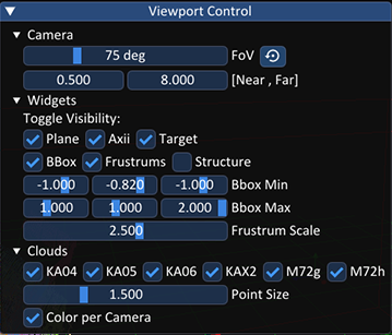
3. Configuring the application’s viewport
Various gizmos can be toggled (i.e. cropping bounding box, ground plane, etc.), as well as 3D stream visualization settings (device color or actual color for the point clouds, etc) from the Viewport Control widget.
4. Recording
Multi-view recordings (Start/Stop) and snapshots (Snapshot) are possible from the Recording widget. You can select a name for the sequence or the snapshot you are going to capture, by typing the name that you desire in the text-field of each operation (Record or Snapshot) and by hitting Enter.
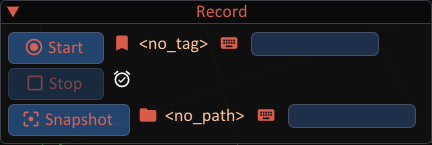
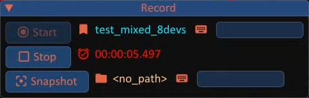
By hitting the Start button, the recording of the live streams begins. By hitting the Snapshot button, only the current frame is saved. The captured sequences and snapshots are saved in the /Data folder, in the directory in which the VolCap application is installed, while snapshots are saved in the /Snapshots folder. Each recording/snapshot is saved in a folder with the current date/time encoded in YY-MM-DD-hh-mm-ss format.
5. Synchronization
Before recording the sensor processing units and the workstation need to be place on a common global timeline. This ensures that even in this distributed sensor acquisition setting, we can replay the recordings without any desync issues. For more information on how to perform this inter-device synchronization step, please see the Synchronization section.
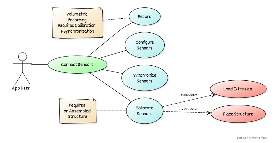
6. Calibration
Similarly, prior to recording, the positions of the sensors need to be spatially aligned to enable volumetric data acquisition. For more information on how to perform this inter-device calibration step, please see the Calibration section.